The M.U.L.D.E.R. Unit: DIY Portable Multi-Sensor
The Idea
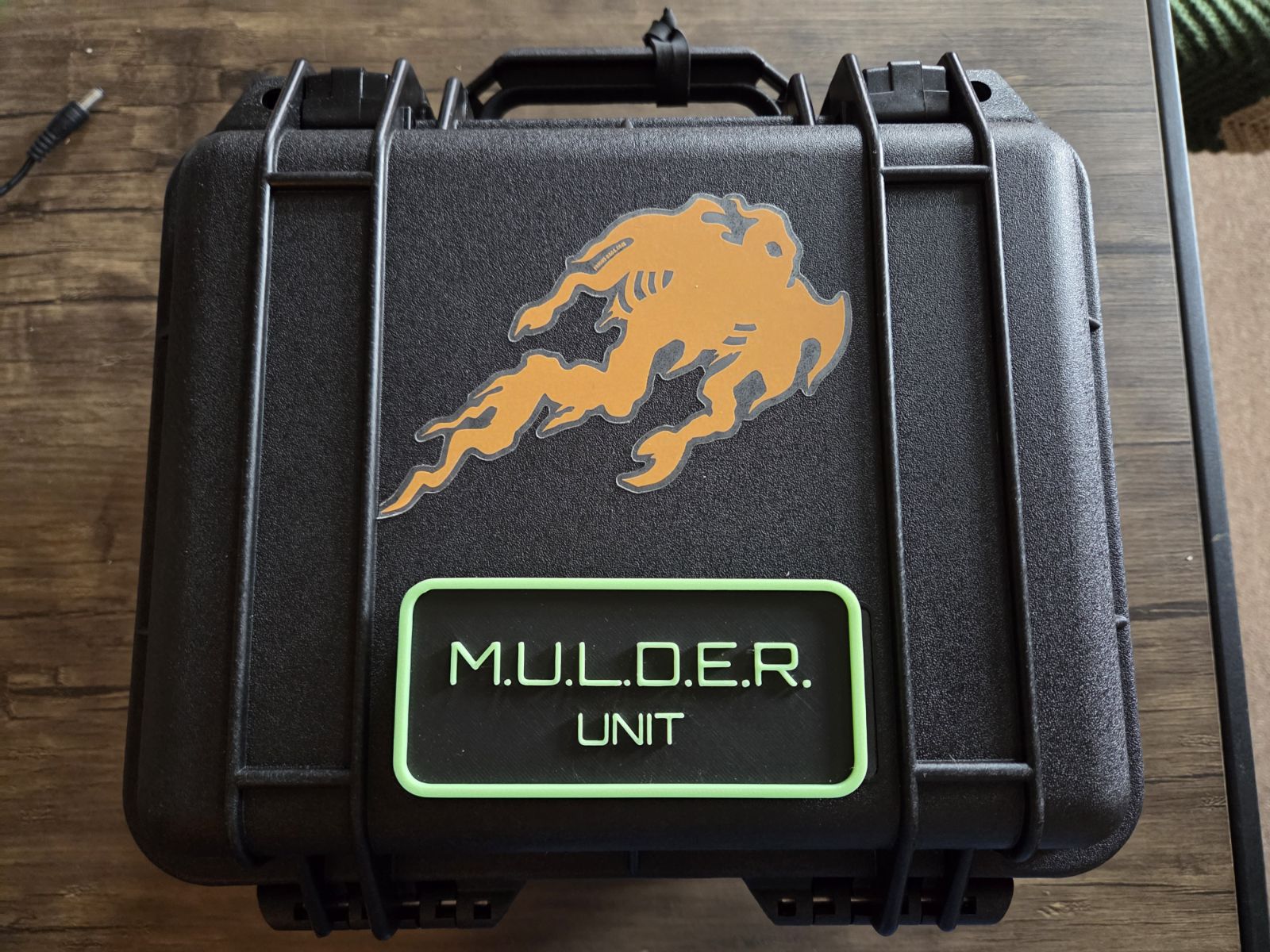
It's a Multi-Use Live Display Emissions Receiver (M.U.L.D.E.R.) that can be deployed on the go, or in the comfort of your own home.
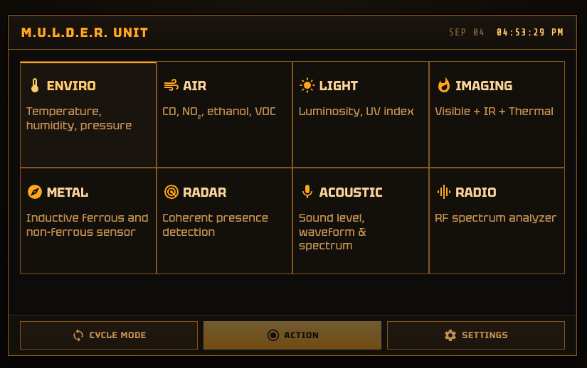
Seen a spook, specter, or ghost? Use the on-board cameras and sensors to scan thermal, infrared, sonic, and many more types of paranormal-adjacent spectra.
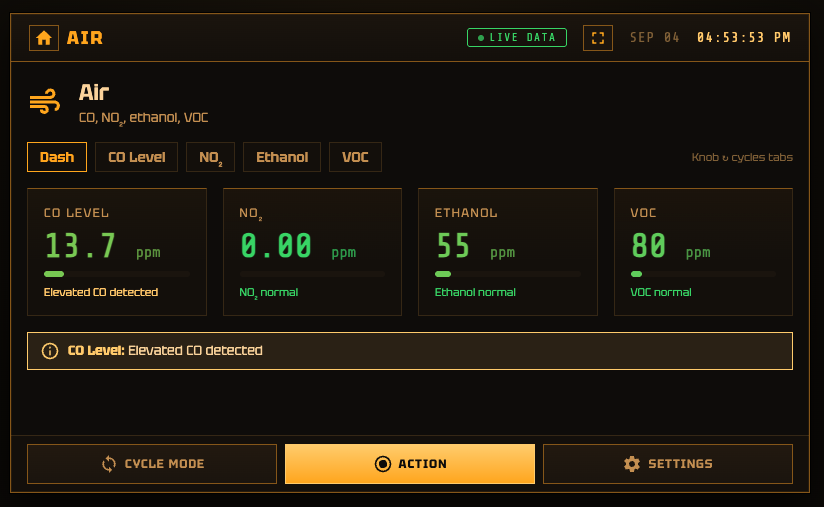
Second guessing what you saw? Attached air quality sensors can measure Carbon Monoxide (a common cause of hallucinations and paranoia) along with Ethanol (portable breathylizer).
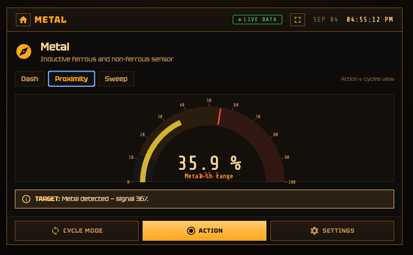
Think you've been abducted or someone's implanted a tracker? Use the short range metal detector (ferrous and non-ferrous) to give yourself a subcutaneous sweep.
The Reality
- ~$450 in hardware
- ~2 months in time from research to completion
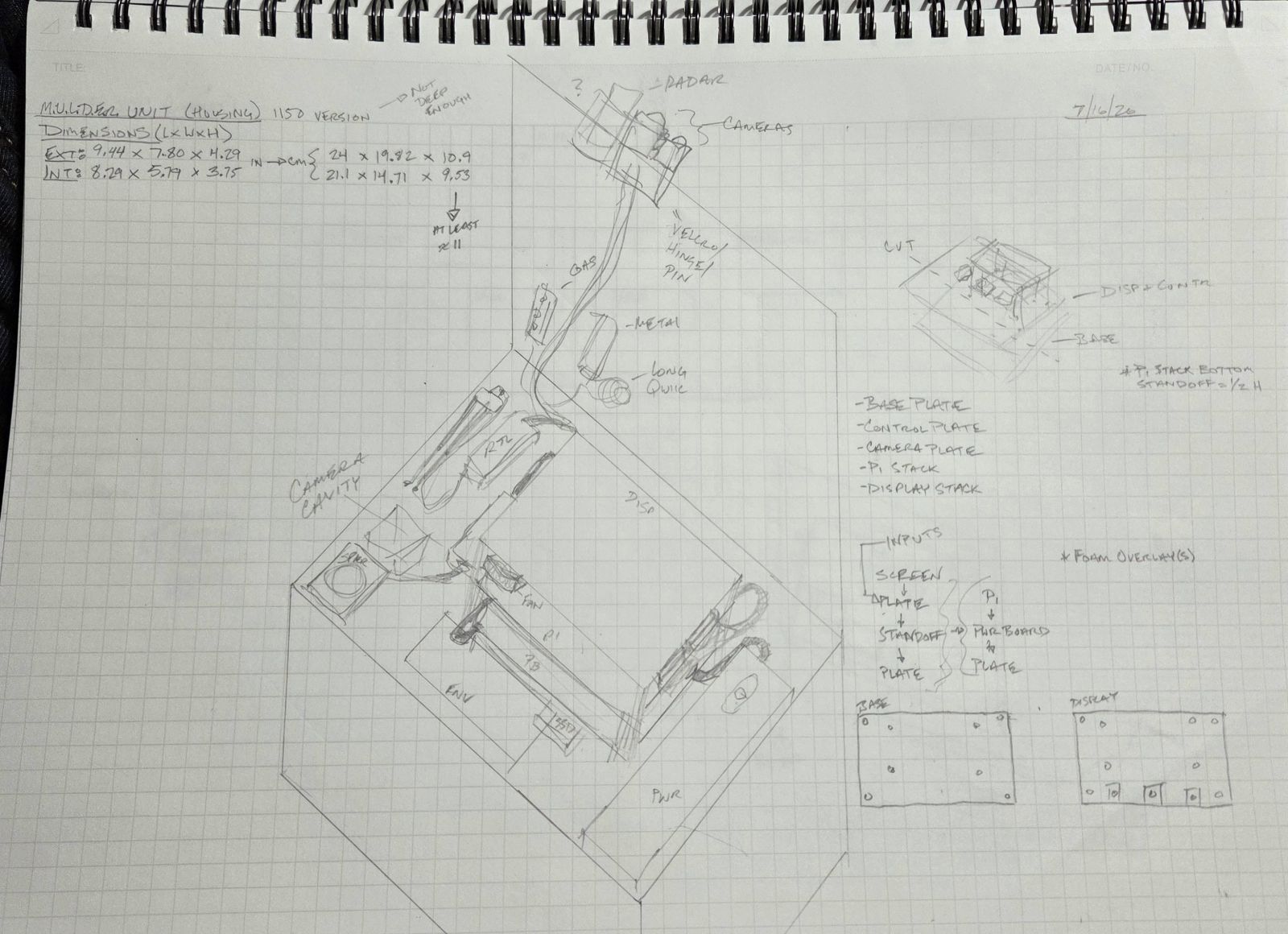
I spent about 2 weeks planning and researching parts before I purchased anything. I also diagrammed out what I thought the parts and connections would look like, a process I found to be a lot of fun even though I've never done any technical drawing before.
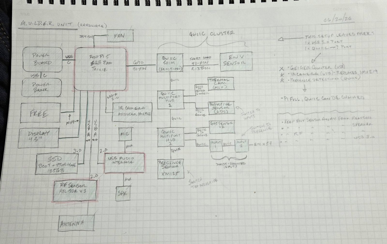
My research paid off with the sensor and Pi purchases, they were all compatible and correct when they arrived. The only flaw was a dead air quality sensor on the Environmental Sensor HAT, but I had a separate gas sensor on the way (the Carbon Monoxide was the big one I wanted) so I didn't bother to return it. Later, the EMF sensor on the same HAT failed, so that was unfortunate, but I elected to remove that sensor from the backend/frontend rather than deal with an overseas return and replacement.
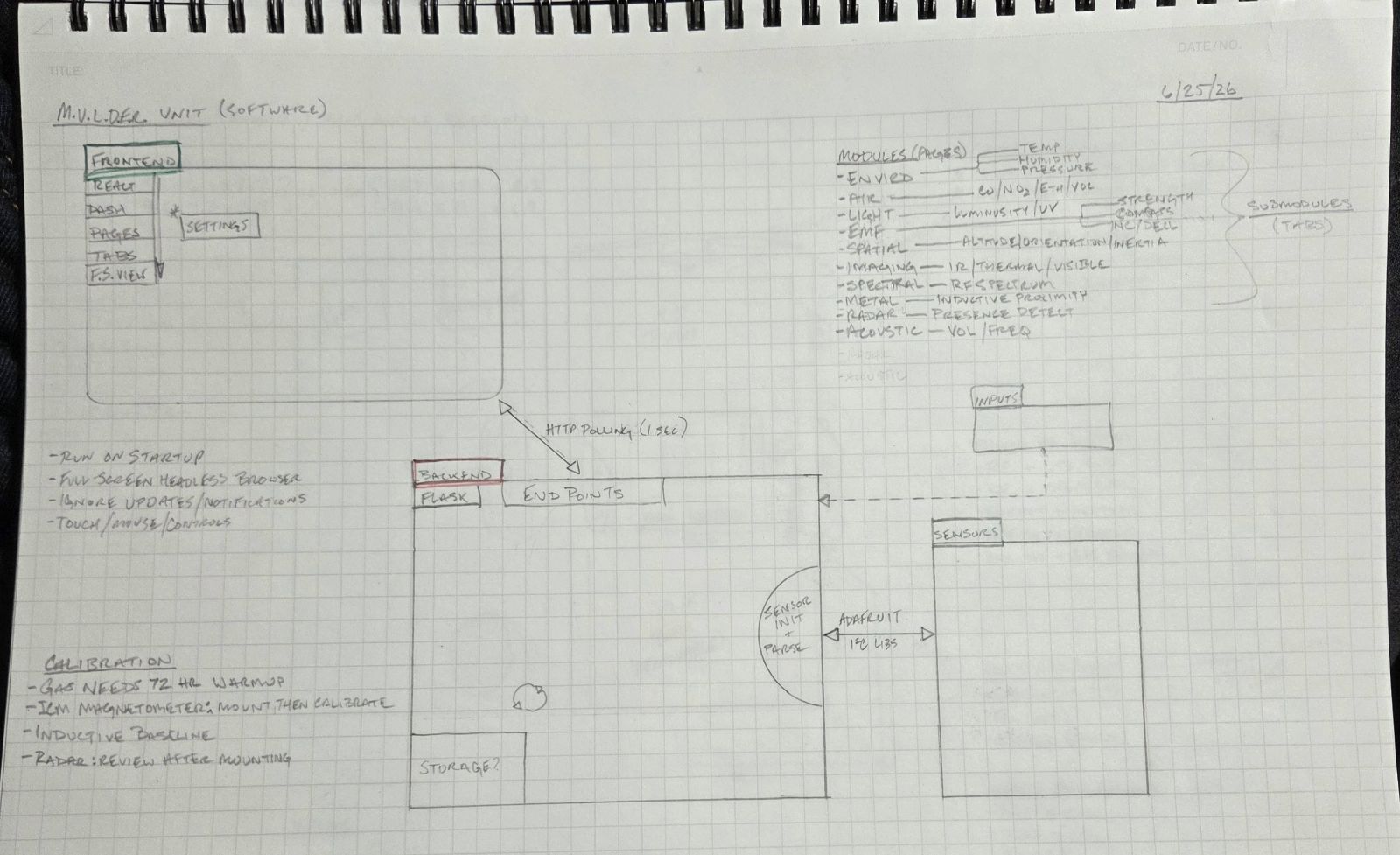
Lots of cables and standoffs were ordered, and a family member was nice enough to 3D print me the mounting boards that everything is attached to, and gradually I was able to start connecting everything together. I wired the Pi to a display, connected a sensor, installed the necessary libraries, and tested a sensor reading with varying levels of success. After troubleshooting was complete, that sensor got its own API endpoint in the Flask backend (build with Claude), and a stubbed out page in the React frontend. Rinse and repeat for every sensor.
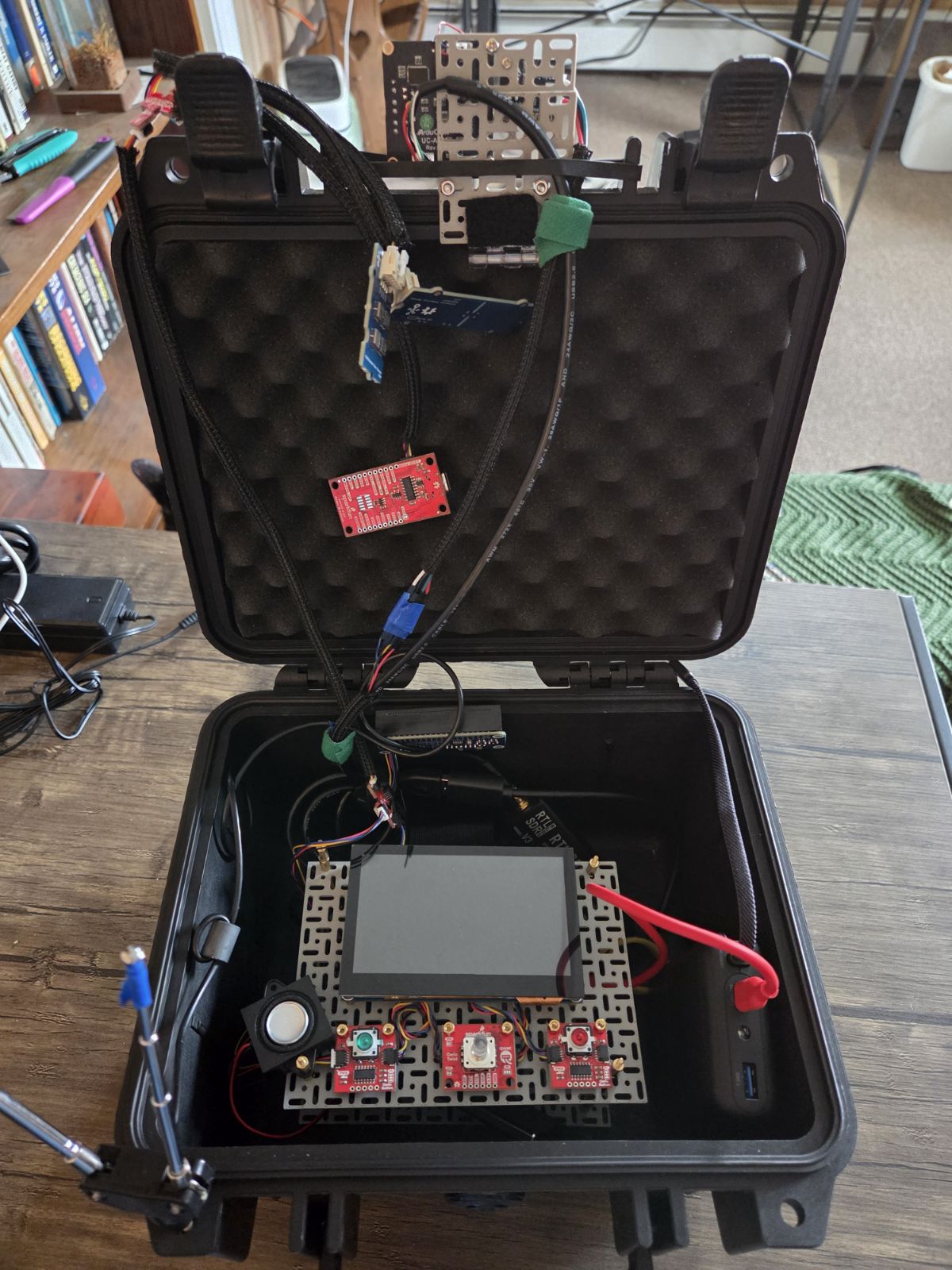
After every sensor was connected and reporting data correctly, and the endpoints were spitting it out in a legible format, I built the React frontend to be a kiosk chrome window containing what is essentially a tabbed interface. The display is a touch screen, and the Pi has bluetooth for connecting a mouse and keyboard, but there are wired hardware controls (a knob and two buttons) to navigate the interface.
The Post-Mortem
While the housing and mounting leaves a lot to be desired (it's my first build), the end result is very satisfying from a software perspective. I am primarily a web developer, and interacting with hardware was a fun challenge that taught me a lot in the process. If I had it to do over again, I think I would try to look for a camera that had day/night/thermal vision in one unit, instead of splitting it across 2 cameras and trying to align their output (it doesn't look great). Other than that I'm pretty happy with it, but I do intend to improve the housing and mounting.
Hardware
Compute, power and enclosure
| Part | Role |
|---|---|
| Raspberry Pi 5 (8GB) | Main computer; runs the sensor API and the kiosk UI, booting from the USB SSD |
| 52Pi/GeeekPi EP-0225 PD power board | Sits between the power bank and the Pi and regulates voltage: takes USB-C PD (15V) or 9–24V DC in and delivers a steady 5V/5A to the Pi, so different power sources can be used without overloading it. Also adds a power button for startup and shutdown |
| INIU 20,000mAh 45W power bank (USB-C PD, built-in USB-C cable) | Portable power |
| Vansuny 500GB USB SSD | Boot drive and storage (microSD as fallback boot) |
| Waveshare 4.3" DSI display | 800×480 touchscreen |
| Raspberry Pi Active Cooler | Pi 5 heatsink and fan (4-pin JST-SH fan header) |
| Pelican 1300 Case | Chassis |
| 3D-printed mounting boards (PCB mounting grid, an Adafruit Swirly clone) | Internal mounting for the boards and sensors |
| 3D-printed name plate (made with The Everything Sign Generator) | Name plate |
Sensors
| Part | Interface | What it measures | UI mode |
|---|---|---|---|
| Waveshare Environment Sensor HAT (BME280, TSL25911, LTR390), moved off the Pi on a 40-pin extension ribbon so the Pi's heat doesn't skew its readings | I²C | Temperature, humidity, pressure, ambient light, UV index | Environmental, Light |
| Seeed Grove Multichannel Gas Sensor v2 | I²C | CO, NO₂, VOC and ethanol, relative to a calibrated baseline | Air Quality |
| Seeed Grove 2-Channel Inductive Sensor (TI LDC1612) | I²C | Inductance shift from nearby metal | Metal Detection |
| SparkFun XM125 (Acconeer A121, 60GHz pulsed coherent radar) | I²C, Presence Detector firmware | Presence and range, 0.3–5m | Radar |
| Seengreat MLX90642-D110 thermal camera (Melexis sensor, 110° field of view) | I²C | 32×24 far-infrared temperature array | Thermal |
| Arducam 1080P Day/Night USB camera (OV2710 sensor, 850nm IR LEDs) | USB | Visible and IR video with automatic IR-cut | Day/Night |
| RTL-SDR Blog V3 (RTL2832U + R820T) + antenna | USB | RF spectrum snapshots and demodulated radio audio | Radio |
| Microphone, built into the speaker | USB, through the audio adapter | Audio waveform and spectrum | Acoustic |
Controls and audio
| Part | Role |
|---|---|
| SparkFun Qwiic Twist (rotary encoder with RGB LED ring) | Twist to navigate on screen, click to toggle full-screen view where available; ring colour follows the active mode |
| SparkFun Qwiic Button ×2 (green, red, each with an onboard LED) | Green advances into a module, red backs out |
| Waveshare touchscreen | Tapping works too, though the knob and buttons suit some modules better |
| Speaker with built-in microphone | Radio audio and interface sound effects; plugs into the audio adapter with its built-in aux cable |
| USB audio adapter | Connects the speaker and microphone to the Pi over USB |
Connections
| Part | Role |
|---|---|
| SparkFun Qwiic SHIM | Bridges the Pi's GPIO header to the Qwiic (I²C) bus |
| SparkFun Qwiic MultiPort 4-port hub ×2, chained | Fans the Qwiic bus out to the sensors and controls |
| SparkFun Qwiic cables, plus a Qwiic-to-female-jumper cable | Bus wiring; the jumper cable is for the MLX90642's non-keyed connector |
| SparkFun Qwiic-to-Grove adapter ×2 | Connects the Grove LDC1612 and gas sensor to the Qwiic bus |
| Adafruit 40-pin GPIO HAT extension ribbon | Moves the Environment Sensor HAT off the Pi's header |
Software
On-device backend (mulder-backend)
- Python + Flask API serving each sensor at its own endpoint; each sensor initialises independently, so a missing one doesn't take the server down
- Lightweight database storing historical sensor readings and screenshots
- Adafruit Blinka / CircuitPython drivers for the BME280, TSL2591 and LTR390
- smbus2 register-level drivers written for the LDC1612 and XM125, which have no Adafruit drivers
- Seengreat MLX90642 C driver, compiled and loaded through Python's
ctypes - rtl-sdr tools (
rtl_sdrfor IQ snapshots with a NumPy FFT,rtl_fmpiped toaplayfor live radio audio) - Server-Sent Events stream that turns Qwiic button and encoder input into UI intents
Interface (mulder-ui)
- React 18 + Vite
- Material UI v5 for components and icons
- Plotly for every sensor chart, spectrogram, waterfall and heatmap
- React Router v6 for mode navigation
- Custom CSS theme sized for the 800×480 display
Operating system and deployment
- Debian Trixie with the labwc Wayland compositor
- Chromium in kiosk mode, fullscreen on boot
- systemd services for the backend and UI, started automatically at power-on